Accelerometer Sensor Driver
The micro:bit v2 has an on-board LSM303AGR e-compass module. Writing device drivers is a common task in our domain, so that is what we are going to do in this exercise. There are open-source drivers available, but we are going to write a new one so you can actually learn how this process works. This is an on-board MEMS sensor. It’s tiny! You can see where it is located on the board on the website. Look for the ST LSM303AGR on the board images.
This is a capable MEMS sensor which has confusing sections in its datasheet. It uses a lot of abbreviations and expects implicit knowledge. This is unfortunately something that is very common in datasheets written by hardware companies. We have looked at the datasheet and extracted the most relevant knowledge by also looking at available drivers provided by the community so you do not have to do this guesswork anymore.
The goal of this exercise is to write a very rudimentary driver which can be used to read the acceleration values. While it might be a bit more relevant to implement the magnetometer reading for our applications (satellite systems without propulsion), the accelerometer gives a nice visualization without requiring a rod magnet to verify sensor readings. The basic principles of reading and converting raw sensor values remains the same and can be transferred to other sensors.
Features of the hardware sensor
Let’s have a look at the feature set of that sensor first by looking at the micro:bit docs:
- e-compass which combines a magnetometer and accelerometer into one package
- Configurable range of 2/4/8/16g
- Configurable resolution of 8/10/12 bits
The sensor also has an output data rate (ODR) configuration which specifies how often the sensor updates its internal value. Let’s make some requirements for our driver to simplify our task:
- Our simple driver will only support +- 2g.
- Only support normal resolution of 10 bits.
- Configurable ODR settings.
The sensor has two communication interfaces: I2C and SPI. However, by looking at the HW schematic:
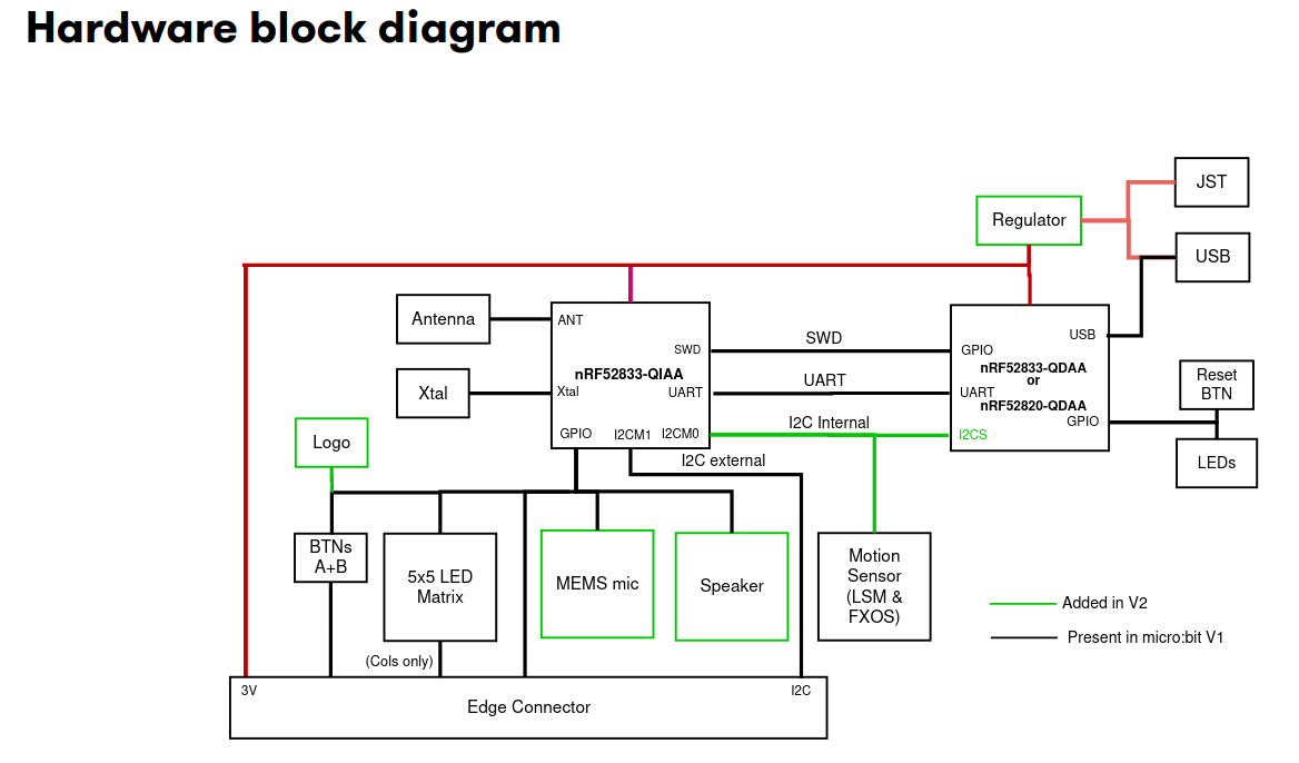
We can see that the sensor is connected through I2C. An in-depth explanation of the I2C (or SPI) bus would exceed the scope of this exercise, but the most relevant key information from a software engineering perspective are summarized here:
- I2C allows communication between multiple devices through two GPIO pins only. One is the data pin which is called the serial data line (SDA) and the other pin is called the serial clock (SCL)
- The most common I2C communication speeds are normal mode with 100 kHz and fast mode with 400 kHz.
- I2C relies on device addressing to allow talking to a single device on a shared bus.
- An I2C transaction can be abstracted with three operations:
read,writeandwrite_read.
The Rust embedded-hal crate provides generic traits that portable device drivers and HAL implementations
need to agree on. You can have a look at how these basic bus properties were captured in the
I2C trait. Notice how its
API functions expect a device address and are named read, write and write_read.
We are not going to use this trait directly for this exercise, but the trait would be relevant if you either want to write a driver which works on multiple hardware platforms, or if you want a driver which works with both exclusive bus access and when sharing the bus with multiple other devices.
Looking at the pin map, we can figure out that the SDA pin is mapped to P0.16 and the SCL pin is mapped to P0.08. There are also external I2C pins, but those are routed to the edge connector and are used to connect external devices.
When it comes to writing device drivers, you will generally wrap the communication driver object
in your driver. For this device, you would wrap some I2C driver. We can omit some abstraction
because we know that we are never going to share the bus,
and we do not want to write a portable driver. This means we can wrap the bus driver provided
by the HAL. Nordic uses a different name for the I2C protocol and calls it TWI (two-wire interface).
There is a twim which provides
support for the Two Wire Interface in master mode, which is relevant for us.
Step 1 - Create the I2C/TWI driver
Open the src/bin/accelerometer.rs file. Start creating the twim driver and storing it into an object named i2c_bus.
We provided all required information, including the pin mapping for the SDA and SCL pin.
The default TWI configuration provided by embassy is sufficient for our purposes. The name of
the peripheral in the library are TWISPI0. You can assume that a TX RAM buffer of 16 or 32 bytes
is sufficient.
If you are struggling with this step and you have not worked through the blinky or the UART echo exercise yet, you should work through those first.
If you do not remember the exact syntax for creating the interrupt bindings, you can look at the embassy example or at the details:
#![allow(unused)]
fn main() {
pub use embassy_nrf::{twim, peripherals};

bind_interrupts!(struct Irqs {
    TWISPI0 => twim::InterruptHandler<peripherals::TWISPI0>;
});
}
Rest of solution:
#![allow(unused)]
fn main() {
    let mut tx_ram_buffer: [u8; 32] = [0; 32];
    let i2c_config = twim::Config::default();
    let i2c_bus = embassy_nrf::twim::Twim::new(
        periphs.TWISPI0,
        Irqs,
        periphs.P0_16,
        periphs.P0_08,
        i2c_config,
        &mut tx_ram_buffer,
    );
}
Step 2 - Create the basic driver object
You are now going to create a driver object instead of just re-using existing library code in your
application. Go into the src/accelerometer.rs file which is part of the crate library. This
file/module is already included in src/lib.rs for you, but it is empty. Start by creating an empty
structure named Accelerometer here.
Then add one field to that structure: The I2C driver you just created. You actually need a lifetime
of Accelerometer now because the I2C driver has a lifetime as well.
#![allow(unused)]
fn main() {
pub struct Accelerometer<'d> {
    i2c: embassy_nrf::twim::Twim<'d>
}
}
Step 3 - Add a constructor
Add a constructor to your driver object by adding a new method which returns Self. In the most
simple form, the constructor could simply take the I2C bus as an input argument and then create and
return itself.
However, we also want to verify that the communication with our device works properly. Sensors
from ST microelectronics commonly have a WHO AM I register which you can read to verify
basic sensor communication. The value read from this register should have a fixed value that
you can check. Your task is to add a constructor which constructs Accelerometer, checks the
communication and returns Result::Ok(Self) on success and some error if the I2C communication fails
or the WHO AM I register value is invalid.
You can use an enum to model an error which can
either be an embassy_nrf::twim::Error
or some WHO AM I error unit variant. Add an asynchronous constructor function and start with an empty
todo!() implementation block.
If you feel confident in your Rust abilities, try to solve this without using hints and intermediate solutions.
The constructor will have a basic form like this, including a suitable initialization error type:
#![allow(unused)]
fn main() {

#[derive(Debug)]
pub enum InitError {
    I2c(embassy_nrf::twim::Error),
    WhoAmIInvalid
}

impl<'d> Accelerometer<'d> {
    // Constructor.
    pub async fn new(mut i2c: embassy_nrf::twim::Twim<'d>) -> Result<Self, InitError> {
        todo!();
        // Implementation
        // ...
    }
}
}
But how do you actually read back this value using I2C? On this device, you can read a register by first sending the register ID you want to read and then reading back one byte.
The register map can be found in the device datasheet. We have included an excerpt of the register map on page 43 for you:
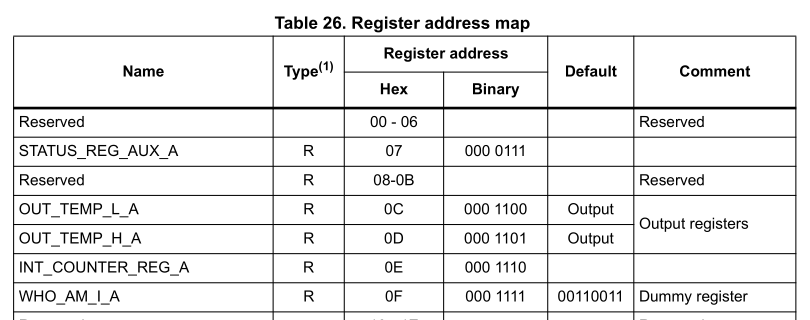
Create a enum which includes the Register IDs, for example one named Register.
Add the WhoAmI variant with the correct register address value. Derive Debug, Copy, Clone,
defmt::Format, PartialEq and Eq on it.
#![allow(unused)]
fn main() {

#[derive(Debug, Copy, Clone, PartialEq, Eq, defmt::Format)]
pub enum Register {
    WhoAmI = 0x0f
}
}
You can add new values to the enum as you need them. Or you put in a lot of work and create a complete one.
AI can help with this menial job.
Now you have everything you need to read the value. You have to use the write_read API.
We already provided hints what you have to send and how much you have to read back. Read back
the WHO AM I register and verify its value. From the datasheet, we can determine the expected value
to be 0b00110011. You can create a constant or associated constant on the Accelerometer object
to store the expected value.
We mentioned that you always have to pass the device address when using the I2C driver
API. For the accelerometer, that address has a fixed value of 0x19 that you can retrieve
from the microbit v2 schematic or from the sensor datasheet. Create an associated constant
ADDR on the Accelerometer driver which has that value.
#![allow(unused)]
fn main() {
impl Accelerometer<'_> {
    pub const ADDR: u8 = 0x19;
}

}
Now you have everything you need to write the constructor. Finish the implementation for the new
method. Return some error variant if the read back
value is not equal to the expected one, and return a driver instance otherwise.
#![allow(unused)]
fn main() {

impl<'d> Accelerometer<'d> {
    pub async fn new(mut i2c: embassy_nrf::twim::Twim<'d>) -> Result<Self, InitError> {
        let mut buf = [0; 1];
        i2c.write_read(Self::ADDR, &[Register::WhoAmIAcc as u8], &mut buf)
            .await?;
        if buf[0] != Self::WHO_AM_I_VALUE {
            return Err(InitError::InvalidWhoAmI);
        }
        Ok(Self { i2c })
    }
}

impl Accelerometer<'_> {
    pub const ADDR: u8 = 0x19;
    pub const WHO_AM_I_VALUE: u8 = 0b00110011;
}
}
The interaction with other registers is comparable. In general if you want to read registers,
you still have to use write_read to select the correct registers, while you can just use
write if you only want to write to a register.
Intermediate solution file:
firmware/exercises/src/accelerometer_step3.rs
Step 4 - Configure the sensor
Now you have a driver instance, but you actually want to read some sensor values. We tried this for you before, and wondered why the accelerometer readings returned all zero. It turns out you need to write some configuration registers to actually enable the device. Let’s do this first.
We extracted the definition of CTRL_REG1_A on page 47 of the datasheet for you:
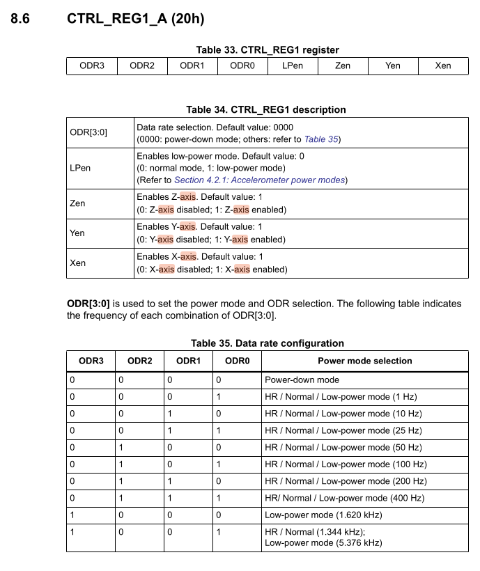
The device is in Power-Down mode on startup. This is the most important control register because it allows us to set the output data rate (ODR), enabling the device and individual axes. The datasheet specifies an 8-bit register configuration.
- Bits 7 down to 4 are the ODR3 to ODR0 configuration bits
- Bit 3 is the low power enable bit
- Bits 2 down to 0 enable the axes Z, Y, and X respectively
We are going to use a crate called bitbybit which provides a declarative way to specify
registers and then provides a convenient API to build the register value which avoids
the need to write bitshifts and masks.
Have a look at the examples from the bitbybit
crate and try to specify this register using bitbybit::bitfield. Adding default = 0x0
inside proc macro attributes also adds a builder API which is useful for us while debug adds
an improved Debug implementation. This can be combined with the
arbitrary-int library.
We can also use bitbybit::bitenum to model the ODR configurations with an enum.
If you have worked with these libraries before, try to create the data structures using those libraries. Otherwise, have a look at the solution and try to understand them by cross-checking them with the register definition we provided you above:
Inside the src/accelerometer.rs library file:
#![allow(unused)]
fn main() {
/// Output data rate configuration.
#[bitbybit::bitenum(u4, exhaustive = false)]
#[derive(Debug)]
pub enum OdrConfig {
    PowerDown = 0b0000,
    Odr1Hz = 0b0001,
    Odr10Hz = 0b0010,
    Odr25Hz = 0b0011,
    Odr50Hz = 0b0100,
    Odr100Hz = 0b0101,
    Odr200Hz = 0b0110,
    Odr400Hz = 0b0111,
    LowPower1620Hz = 0b1000,
    HrNormal1344HzLowPower5376Hz = 0b1001,
}

#[bitbybit::bitfield(u8, default = 0x0, debug)]
pub struct ControlReg1 {
    #[bits(4..=7, rw)]
    odr: Option<OdrConfig>,
    #[bit(3, rw)]
    low_power_enable: bool,
    #[bit(2, rw)]
    z_enable: bool,
    #[bit(1, rw)]
    y_enable: bool,
    #[bit(0, rw)]
    x_enable: bool,
}
}
Now you have everything you need to update the register. The excerpt of the datasheet also
shows the register ID, which is 0x20. Add the CtrlReg1 variant to the Register enumeration
you created before. You can now use the builder API on ControlReg1 to build the target
configuration.
Use i2c.write inside the constructor to write the ControlReg1 to the right register ID,
using an ODR of 100 Hz. Remember that you can write a register by sending the register ID as the
first byte, and the register value as the second byte.
Updated constructor:
#![allow(unused)]
fn main() {
    pub async fn new(mut i2c: embassy_nrf::twim::Twim<'d>) -> Result<Self, InitError> {
        let mut buf = [0; 1];
        i2c.write_read(Self::ADDR, &[Register::WhoAmIAcc as u8], &mut buf)
            .await?;
        if buf[0] != Self::WHO_AM_I_VALUE {
            return Err(InitError::InvalidWhoAmI);
        }
        i2c.write(
            Self::ADDR,
            &[
                Register::CtrlReg1 as u8,
                ControlReg1::builder()
                    .with_odr(OdrConfig::Odr100Hz)
                    .with_low_power_enable(false)
                    .with_z_enable(true)
                    .with_y_enable(true)
                    .with_x_enable(true)
                    .build()
                    .raw_value(),
            ],
        )
        .await?;
        Ok(Self { i2c })
    }
}
Intermediate solution file:
firmware/exercises/src/accelerometer_step4.rs
Step 5 - Read the raw accelerometer values
Now we can read the raw sensor values. By looking at the register mapping on page 43 of the datasheet again, we can figure out the base addresses of the sensor readout:
- OUT_X_L_A at 0x28
- OUT_X_H_A at 0x29
- OUT_Y_L_A at 0x2A
- OUT_Y_H_A at 0x2B
- OUT_Z_L_A at 0x2C
- OUT_Z_H_A at 0x2D
As you can see, those registers are consecutive. The datasheet mentions that the data is provided
as a signed two-complemented number which is left-adjusted. They are also ordered in little endian
format, where the low byte is at the smaller memory address. This is relevant for creating
the raw i16 binary value from the raw bytes in the correct order.
We could perform 6 individual reads on the addresses specified above. However, the device
has a register auto-increment feature that we can use. By setting bit 7 in the register ID
value to 1, we can tell the device to automatically increment the device address for the next
read. This allows us to read all 6 registers with one I2C write_read transaction.
Create a AUTO_INCREMENT_MASK constant or associated constant and set it to 0x80 or
0b1000_0000. Now add a method named read_raw to your driver which will return the sensor readout.
The _raw suffix makes it clear that those are raw sensor values which are not worth much on
their own and still require some processing and conversion to proper units.
What do we actually return? A simple way would be to return a (i16, i16, i16) tuple.
You can also create a dedicated named structure and this is what we are going to do.
Add a structure named ReadoutRaw, which has x, y and z public fields.
You can add common derives like Debug, Copy, Clone, defmt::Format as well.
#![allow(unused)]
fn main() {
#[derive(Debug, defmt::Format)]
pub struct ReadoutRaw {
    pub x: i16,
    pub y: i16,
    pub z: i16,
}
}
Now you can specify the async read_raw method for your driver as well.
#![allow(unused)]
fn main() {
    pub async fn read_raw(&self) -> Result<ReadoutRaw, Error> {
        todo!();
    }
}
The method we specified in our solution only required a shared reference of the driver.
This makes sense, because we are not configuring anything in the driver. However, we still require
mutable access to the wrapped i2c driver because that is just the function prototype of the
write_read method. We can fix this by using interior mutability.
Wrap the i2c field of the structure in a core::cell::RefCell. You also have to update the constructor.
#![allow(unused)]
fn main() {
use core::cell::RefCell;

pub struct Accelerometer<'d> {
    i2c: RefCell<embassy_nrf::twim::Twim<'d>>,
}
}
and inside constructor method, use core::cell::RefCell::new(i2c) to wrap the i2c driver in
a RefCell.
You can get a mutable reference to the i2c driver using borrow_mut on the
field without requiring mutable access to the driver now.
Next, you can write the actual implementation which reads the sensor values. Remember that you can
read all 6 registers with one transaction by setting the AUTO_INCREMENT_MASK bit on the register
start ID, which would be the OUT_X_L_A register in our case. Now you just have to specify an
appropriate receive buffer size to read 6 words starting at that address.
After you have read the 6 bytes into a raw buffer, you need to extract and convert them into
a raw i16 for further conversion. You can use i16::from_le_bytes to do this conversion.
#![allow(unused)]
fn main() {

impl Accelerometer<'_> {
    pub const ADDR: u8 = 0x19;
    pub const WHO_AM_I_VALUE: u8 = 0b00110011;
    pub const AUTO_INCREMENT_MASK: u8 = 0x80;

    pub async fn read_raw(&self) -> Result<ReadoutRaw, Error> {
        let mut buf = [0; 6];
        self.i2c
            .borrow_mut()
            .write_read(
                Self::ADDR,
                &[Self::AUTO_INCREMENT_MASK | Register::OutXLowAcc as u8],
                &mut buf,
            )
            .await?;
        Ok(ReadoutRaw {
            x: i16::from_le_bytes([buf[0], buf[1]]),
            y: i16::from_le_bytes([buf[2], buf[3]]),
            z: i16::from_le_bytes([buf[4], buf[5]]),
        })
    }
}
}
Intermediate solution file:
firmware/exercises/src/accelerometer_step5.rs
Step 6 - Convert and read the values in the SI unit mg
Those raw values are not worth much by themselves. There are some conversion steps that we need to do. The datasheet specifies the raw binary format as a left-adjusted signed two-complement number. There are 2 conversion steps required here:
- Eliminate trailing bytes depending on the selected resolution. We specified that this device has different resolution rates represented by bits. We can assume normal resolution (10-bits). This means that our relevant value will be placed on bit positions 15 downto 6. The simplest way to perform this scaling is by right-shifting by 6.
- Scale the result to achieve our value in SI units. The datasheet specifies the sensitivity for a full scale of +- 2g in mg per digit. You need to multiply the raw value with that table value. However, that table value also needs to linearly scale with the full scale.
A general formula for the acceleration which should have been provided in the datasheet but is not for mysterious reasons, can therefore be written as:
$$ A_{mg} = (R \gg n) \times \left( S_{2g} \times \frac{FS}{2} \right) $$
- R is the raw value
- S is the sensitivity value you can take from the table below. It is called SO in the table, which is an abbreviation for scale output.
- n is the resolution shift, which is 16 minus the number of resolution bits, e.g. 6 for 10-bit resolution.
- FS is the full scale value, e.g. 2 for +- 2g full scale.
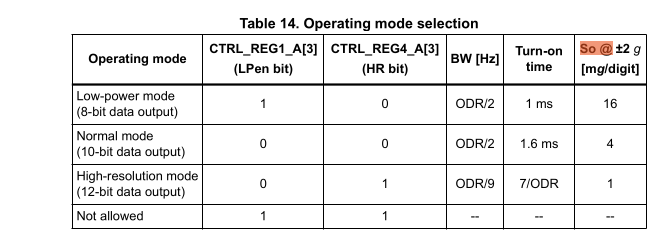
You can assume FS to be +-2g which is the default full scale for the sensor.
We would like to write our driver in a way that allows changing the resolution and full scale
in the future. Introduce two new enumerations which allow modelling this: A Mode enumeration
and a FullScale enumeration in the library. The Mode enumeration should include the Power Down,
Low Power, Normal and High Resolution Mode. The FullScale should include all full scales that this
device supports. You cannot specify enum variants with leading numbers, but you can use a
leading underscore to allow this. In the full scale enumeration, assign the actual full scale
value as the enum value.
#![allow(unused)]
fn main() {
#[derive(Debug, Clone, Copy, defmt::Format)]
pub enum FullScale {
    _2g = 2,
    _4g = 4,
    _8g = 8,
    _16g = 16,
}

#[derive(Debug, Clone, Copy, PartialEq, defmt::Format)]
pub enum Mode {
    /// Power down
    PowerDown,
    /// Low power (8-bit)
    LowPower,
    /// Normal mode (10-bit)
    Normal,
    /// High resolution (12-bit)
    HighResolution,
}
}
Now add a resolution_shift method to the Mode structure which returns the right-shift
value n that you have to apply to the raw value.
Then, add a scale_multiplier method to the Mode enumeration which also takes a FullScale as
an argument and calculates the final multiplier which needs to be applied to the shifted raw
value.
#![allow(unused)]
fn main() {
impl Mode {
    pub const fn resolution_shift(&self) -> i16 {
        match self {
            Mode::PowerDown => 0,
            Mode::HighResolution => 4,
            Mode::Normal => 6,
            Mode::LowPower => 8,
        }
    }

    /// The table 14 specifies the scale output values at += 2g in mg/digit.
    ///
    /// At higher full scales, that value needs to be scaled as well. When using a full scale
    /// of 2, notice how the full scale cancels out with the division and you achieve the table
    /// values.
    pub const fn scale_multiplier(&self, full_scale: FullScale) -> u32 {
        let full_scale = full_scale as u32;
        match self {
            Mode::PowerDown => 1,
            Mode::LowPower => (16 * full_scale) / 2,
            Mode::Normal => (4 * full_scale) / 2,
            Mode::HighResolution => (1 * full_scale) / 2,
        }
    }
}
}
Now add a mode and full_scale field to your driver. Those have fixed values
for now, but you could make them configurable at a later point.
#![allow(unused)]
fn main() {
/// Driver for the LSM303AGR e-compass.
pub struct Accelerometer<'d> {
    i2c: RefCell<embassy_nrf::twim::Twim<'d>>,
    full_scale: FullScale,
    mode: Mode,
}
}
In the constructor, simply hardcode those fields to the default values the device has at startup, which is +- 2g full scale and normal resolution mode.
Now, we will introduce a higher-level type which can be used to read the accelerometer values
in SI units. Add a new structure to your library called Readout. This structure should
include a raw field with the ReadoutRaw type, a full_scale and a mode field.
#![allow(unused)]
fn main() {
#[derive(Debug, defmt::Format)]
pub struct Readout {
    raw: ReadoutRaw,
    full_scale: FullScale,
    mode: Mode,
}
}
Now add the following API methods for Readout:
x_mgwhich returns X axis value in mg as ani32.y_mgwhich returns Y axis value in mg as ani32.z_mgwhich returns Z axis value in mg as ani32.xyz_mgwhich returns the value of all axes in mg as a(i32, i32, i32)
Use the formula we specified above and the methods we added to do this.
#![allow(unused)]
fn main() {
impl Readout {
    /// X axis readout in mg.
    pub const fn x_mg(&self) -> i32 {
        (self.raw.x >> self.mode.resolution_shift()) as i32
            * self.mode.scale_multiplier(self.full_scale) as i32
    }

    /// Y axis readout in mg.
    pub const fn y_mg(&self) -> i32 {
        (self.raw.y >> self.mode.resolution_shift()) as i32
            * self.mode.scale_multiplier(self.full_scale) as i32
    }

    /// Z axis readout in mg.
    pub const fn z_mg(&self) -> i32 {
        (self.raw.z >> self.mode.resolution_shift()) as i32
            * self.mode.scale_multiplier(self.full_scale) as i32
    }

    /// XYZ axis readout in mg.
    pub const fn xyz_mg(&self) -> (i32, i32, i32) {
        (self.x_mg(), self.y_mg(), self.z_mg())
    }
}
}
Finally, we want to have a convenience method called read on our driver which
returns this Readout structure. Add that method and re-use the read_raw method
that you have already written to initialize the raw field of the Readout structure.
You can initialize the full_scale and mode field from the cached values of the driver.
#![allow(unused)]
fn main() {
impl Accelerometer<'_>
    // (other functions...)

    pub async fn read(&self) -> Result<Readout, Error> {
        Ok(Readout {
            raw: self.read_raw().await?,
            full_scale: self.full_scale,
            mode: self.mode,
        })
    }
}
}
Step 7 - Print the accelerometer values inside a loop periodically
We finally have everything we need to periodically read the sensor values.
Go ahead and create the driver you have written inside your example application using the constructor
you have written.
The datasheet mentions a start-up time of 1.6 ms for our configuration.
Call the read method periodically inside a loop and print the xyz values using the
xyz_mg method and defmt.
#![allow(unused)]
fn main() {
    let accelerometer = Accelerometer::new(i2c_bus)
        .await
        .expect("creating motion sensor driver failed");
    // For normal mode, 1.6 ms turn-on time.
    Delay.delay_us(1600).await;

    loop {
        match accelerometer.read().await {
            Ok(reading) => {
                defmt::info!("Accelerations (mg): {}", &reading.xyz_mg());
            }
            Err(e) => {
                defmt::error!("i2c error: {}", e);
            }
        };
        Timer::after_millis(50).await;
    }

}
Finishing Up
If you have done everything correctly, you should see output like this:
-- micro:bit Accelerometer application --
0.003967 [INFO ] Accelerations (mg): (-48, -232, 980) (accelerometer_solution src/bin/accelerometer_solution.rs:43)
0.055694 [INFO ] Accelerations (mg): (-44, -228, 984) (accelerometer_solution src/bin/accelerometer_solution.rs:43)
Your acceleration values may vary slightly based on the orientation of your micro:bit. Regardless, you should measure an acceleration of around 1g, which is the normal force that counteracts gravity when the device rests on a surface.
You can now try things like shaking the device to see how the x and y axis react to this. If you have something to cushion the fall, you could also do a freefall test, which should make the 1g counter force you normally see disappear while the device is free-falling. You might also see spikes when the micro:bit is suddenly decelerated after it hits a surface after free-falling.
You might wonder why an e-compass module has an accelerometer. You can actually use an accelerometer to account for device tilt combined with the magnetometer for the north direction measurement. This is a basic form of sensor fusion which can be used to improve the quality of the compass.